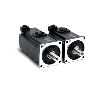


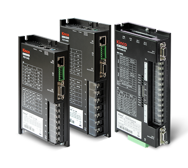
Servo Motors
Servo Drive

Servo Drive
Motor Control
Power Range
DC Voltage
Communication
.png)

.png)


| Model | FD114S-☐B-00■ | FD124S-☐B-00■ | FD134S-☐B-00■ | FD144S-☐B-00■ | FD164S-☐B-000 | |
| Rated Input Voltage | 24VDC – 60VDC | |||||
| Rated Output Current | Max. Continuous Output Current (rms) | 5A | 15A (Up to 12A without auxiliary radiator) | 25A (Up to 20A without auxiliary radiator) | 40A (Up to 30A without auxiliary radiator) | 80A (Up to 60A without auxiliary radiator) |
| Peak Current (PEAK) | 12Ap | 48Ap | 80Ap | 120Ap | 240Ap | |
| Feedback Signal | 2500P/R (incremental differential 5V encoder): magnetic encoder; absolute encoder (for FD1X4S-CB-005 and FD1X4S-EB-005) | |||||
| Brake Chopper | An external braking resistor (depending on the working conditions, mainly used for quick start and stop), the braking voltage absorption point is 73V (FD164S is 63V) (software setting). | |||||
| Brake Chopper Threshold | DC73V ± 2V(default value, can be set) | DC63V±2V (default value, can be set) | ||||
| Over-voltage Alarm Voltage | DC83V ± 2V | DC70V ± 2V | ||||
| Under-voltage Alarm Voltage | DC18V±2V | DC18V±2V | ||||
| Cooling Method | Natural cooling Remark1:The output currents of FD124S, FD134S and FD144S are 15Arms, 25Arms and 40Arms respectively. The value measured on an oxide black 6063 aluminum plate of 300mm*300mm*10mm. 2: The output current of FD164S is 80Arms, the drive needs to be installed on the auxiliary radiator. The length*width*height is the value measured on an oxide black 6063 aluminum plate of 400mm*400mm*10mm. | |||||
| Weight (kg) | 0.3 | 0.3 | 0.6 | 0.9 | 1.68 | |
| General Functions | Input Specification | 4-channel digital input, common to COMI terminal, high level: 12.5-30VDC, low level: 0-5VDC, maximum frequency: 1KHz, input impedance: 5KΩ. (the brake motor drive is a 3-way digital input) | ||||
| Input Function | Freely define as needed, the Functions are as follows: drive enable, drive error reset, drive working mode control, speed loop proportional Input Function control, positive limit, negative limit, origin signal, command reversal, internal speed segment control, internal position segment control, emergency stop, start to find origin, command activation, electronic gear ratio switching, gain switching | |||||
| Output Specification | 2 digital outputs, brake motor drive is 1 digital signal output | |||||
| Pulse Direction Control | Pulse+direction, CCW+CW, A phase+B phase (3.3V – 24V) Note: Only FD1X4S-L☐-000 supports this Function | |||||
| Output Function | Freely define according to needs, the Functions are as follows: drive ready, drive error, motor position arrives, motor zero speed, motor holding brake, motor speed arrives, index Z signal appears, maximum speed limit reached in torque mode, motor lock shaft, motor limit bit center, origin found. | |||||
| RS232 | The default baud rate is 38400 and the maximum baud rate is 115.2K. Can use Kinco host computer software for linking, or use custom protocol to communicate with the controller. | |||||
| Protective Function | Overvoltage protection, undervoltage protection, motor overheating (I2T) protection, short circuit protection, drive overheating protection, etc. | |||||
| Bus Communication | Modbus/RS485 | Maximum support 115.2K baud rate, can use Modbus RTU protocol to communicate with the controller. | ||||
| CAN BUS | Maximum support 1M baud rate, can use CANopen protocol to communicate with the controller | |||||
| EtherCAT | Support CoE (CiA402 protocol) and CSP/CSV/PP/PV/PT/HM mode, the communication speed is 100M. | |||||
| Use Environment | Operating Temperature | 0 – 40℃ | ||||
| Storage Temperature | -10℃ – 70℃ | |||||
| Humidity (no condensation) | Below 90%RH | |||||
| IP Ratings | IP20 | |||||
| Installation Site | Dust-free and dry place (such as electrical cabinet) | |||||
| Installation Method | Vertical installation or horizontal installation | |||||
| Height | The rated working altitude is below 1000m. When the working altitude is above 1000m, every 100m rise, it needs to be derated by 1.5%. The maximum working altitude is 4000m above sea level. | |||||
| Atmospheric Pressure | 86kpa – 106kpa | |||||
| Note: ☐ =A:without brake ■ =B:with brake | ||||||
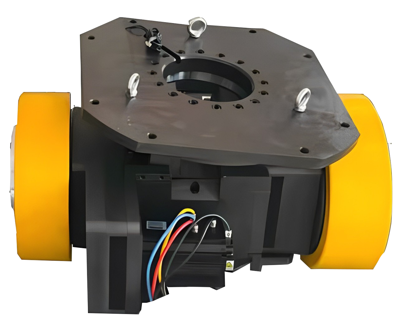
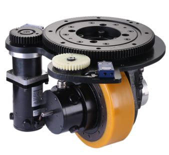
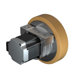
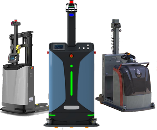
Discover the future of AGV technology with ATOMBOTIX