Author: ATOMBOTIX
Time: 2026-04-19
Share


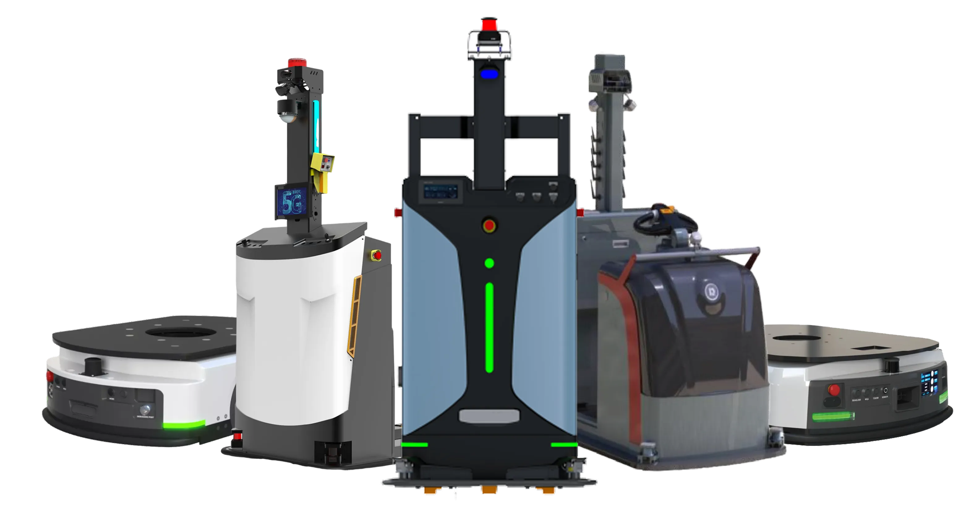
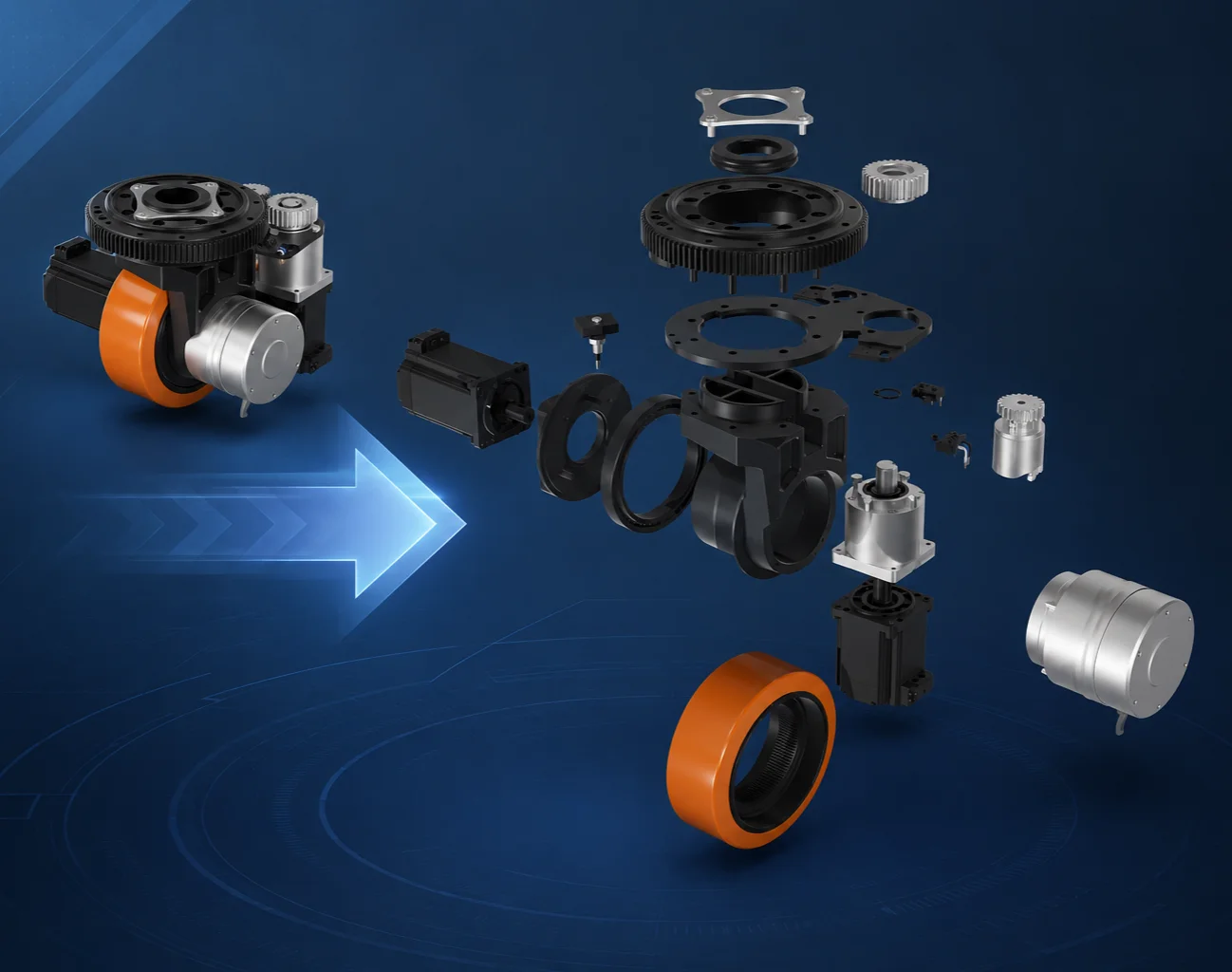
An AGV Steering Drive Wheel Module is a highly integrated electromechanical unit that combines driving and steering functions into a single compact assembly, enabling both vehicle propulsion and directional control.
It is widely used in AGVs, Autonomous Mobile Robots (AMRs), forklifts, and other mobile robotic platforms.
The assembly mainly consists of two core systems:
Traction System
Steering System
The traction system provides the driving force required for vehicle movement, while the steering system controls wheel orientation to achieve directional adjustment.
To ensure precise control and reliable operation, both systems are equipped with sensing, feedback, and protection mechanisms.
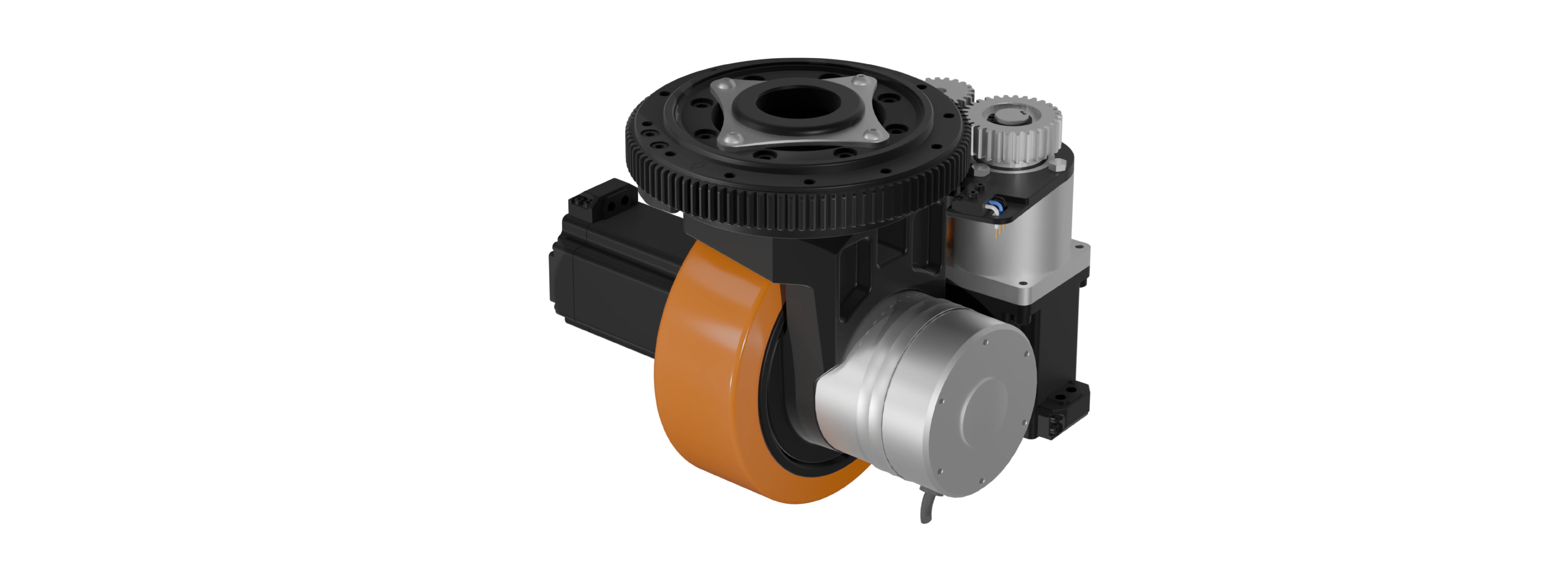
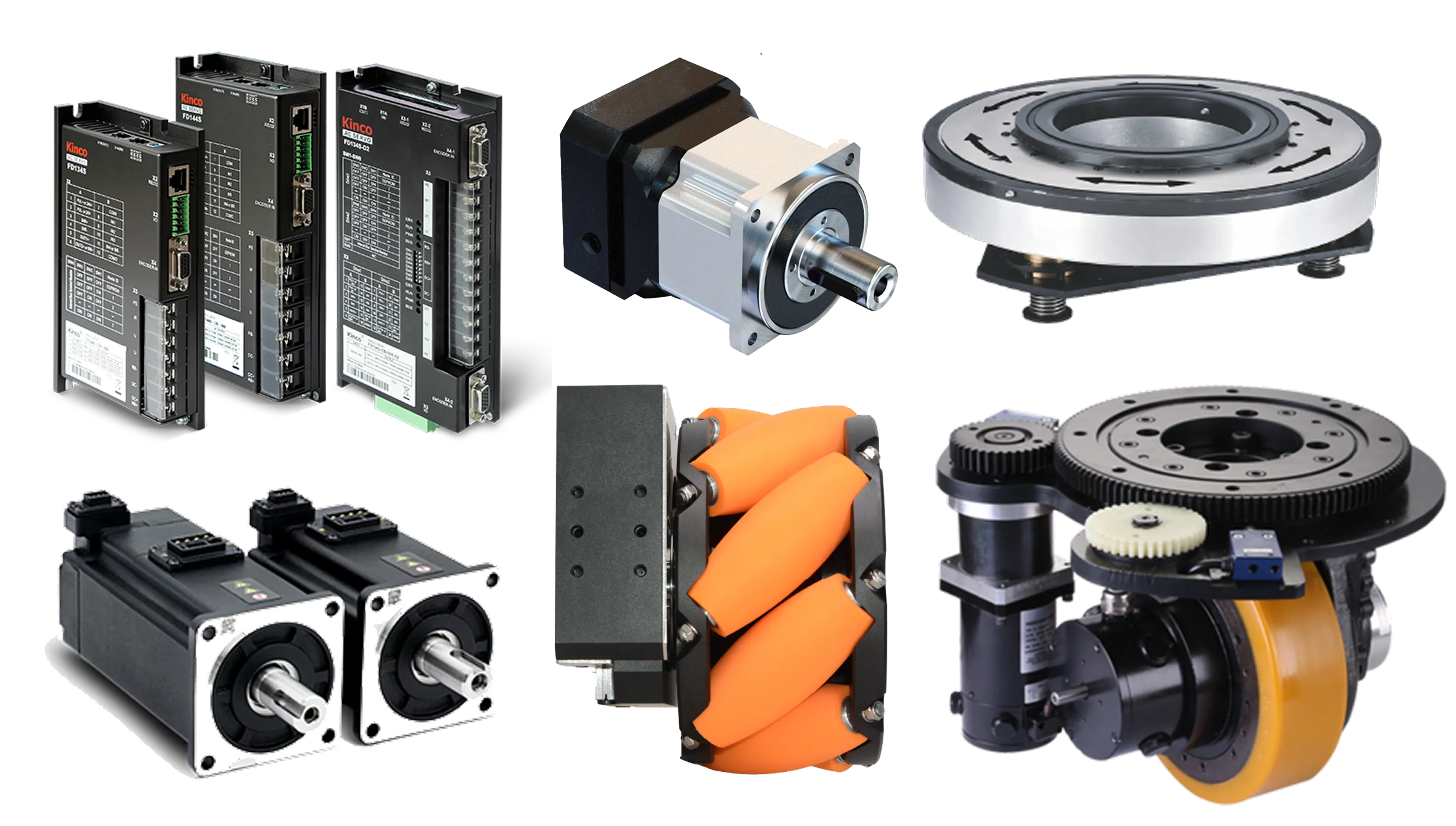
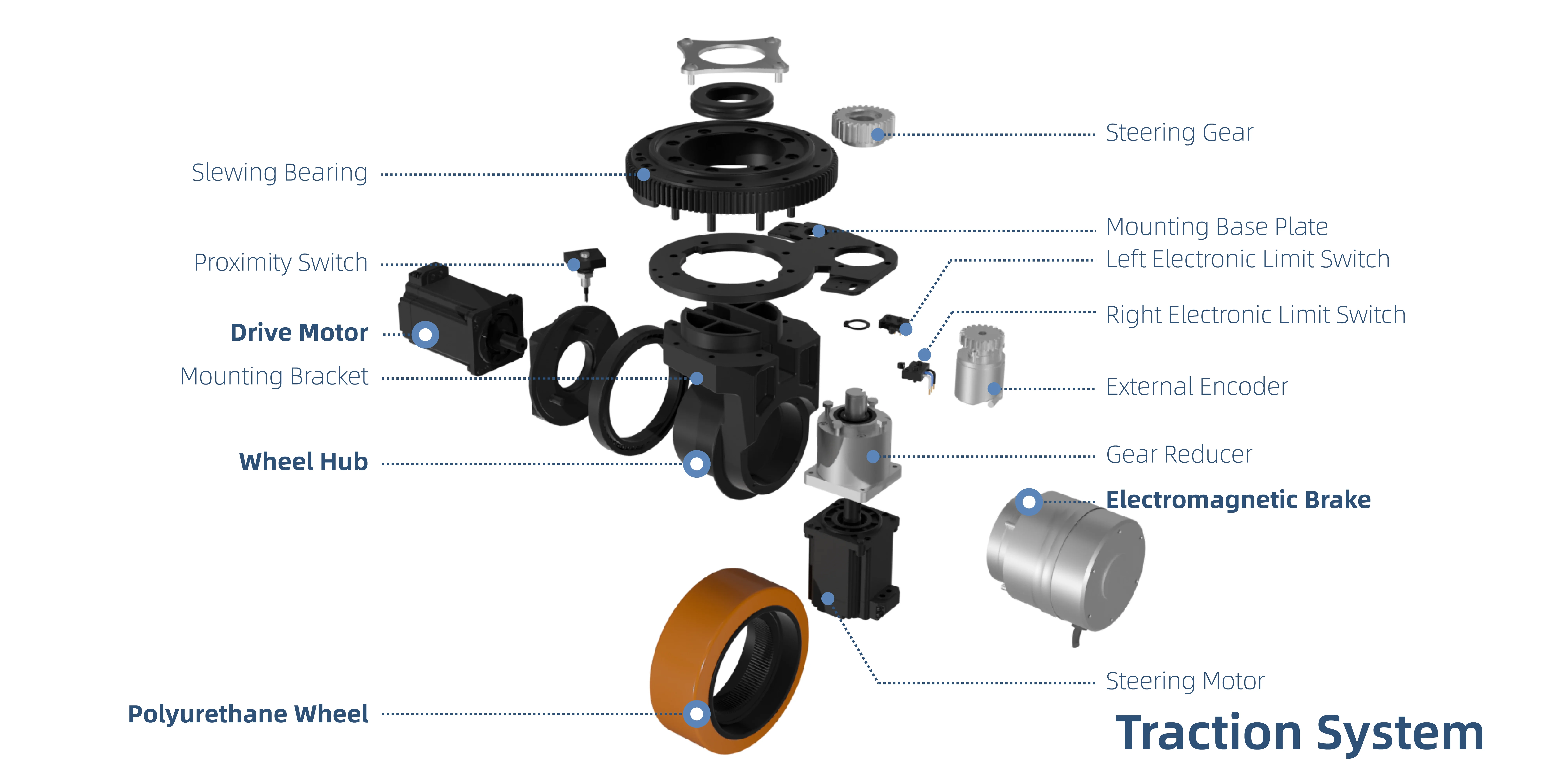
The traction system is responsible for generating the driving force required for vehicle forward and reverse motion. It mainly consists of the drive motor, reducer (gearbox), wheel hub, tire, brake, and encoder.
The drive motor is controlled by an external motor driver and generates rotational torque, which is transmitted through the reducer to the wheel, thereby producing traction force and enabling vehicle movement.
The encoder provides accurate feedback signals to the servo drive for closed-loop motion control, ensuring stable and precise vehicle operation.
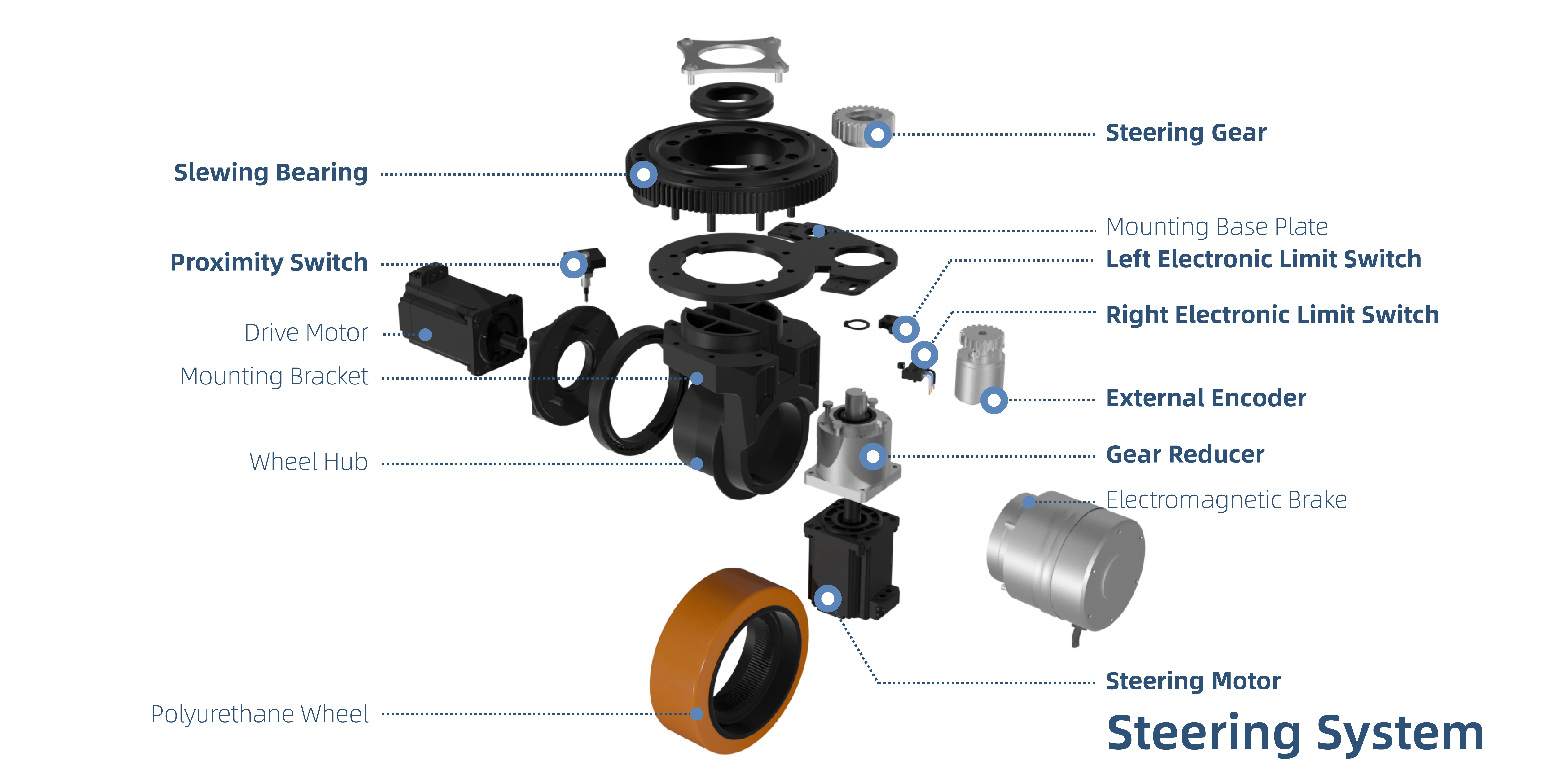
The steering system is responsible for controlling wheel orientation, enabling directional adjustment of the vehicle.
It mainly consists of the steering motor, steering reducer, slewing bearing, steering gear mechanism, and limit protection mechanisms, including electronic and mechanical limits.
The steering motor generates steering torque, which is transmitted through the steering reducer and gear mechanism to rotate the wheel assembly about the center axis of the slewing bearing, thereby achieving precise steering angle adjustment.
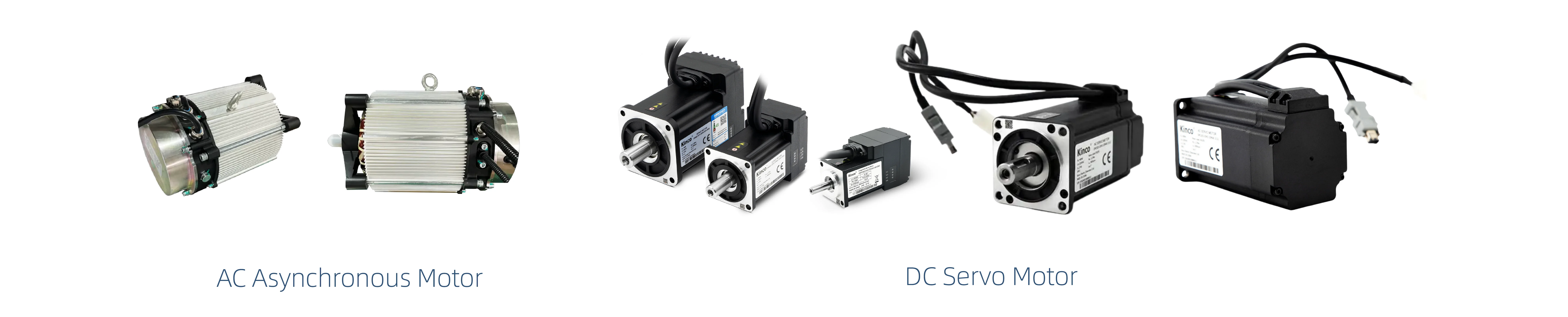
The drive motor is the core power source of the traction system and typically adopts very accessible 24V AC Asynchronous motor, or precise 48V DC servo motor.
The motor output shaft transmits torque to the reducer, which reduces speed and amplifies torque before delivering it to the wheel for vehicle propulsion.
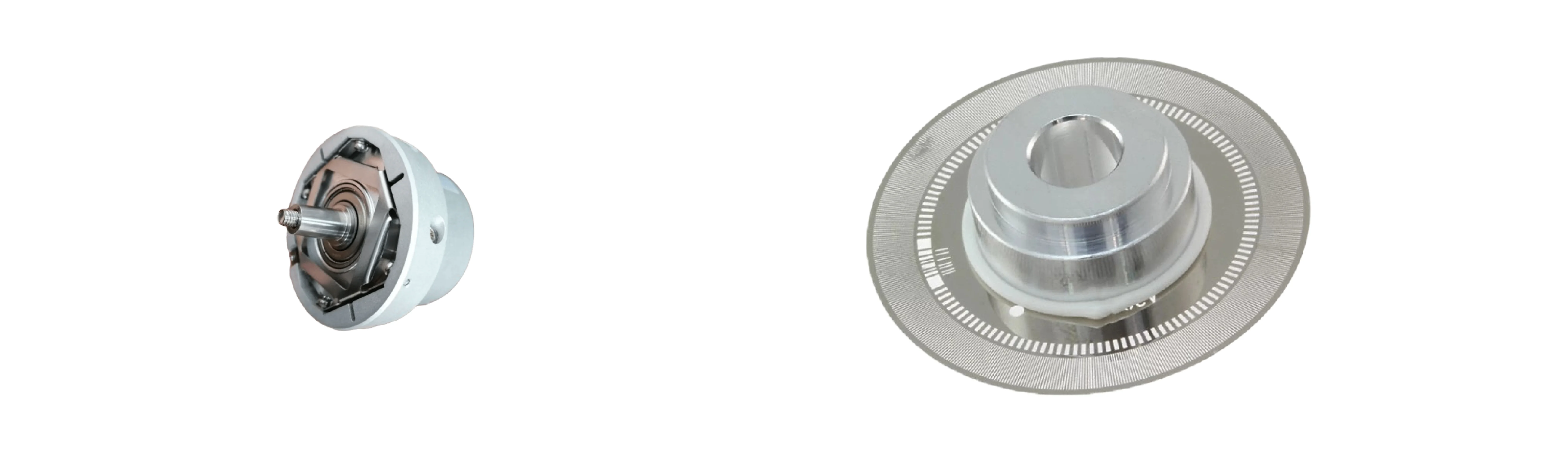
The encoder is integrated into the drive motor and measures the position of the motor rotor.
Its feedback is used by the motor drive to calculate motor speed and rotational direction and to perform closed-loop speed control, supporting stable and precise vehicle movement.
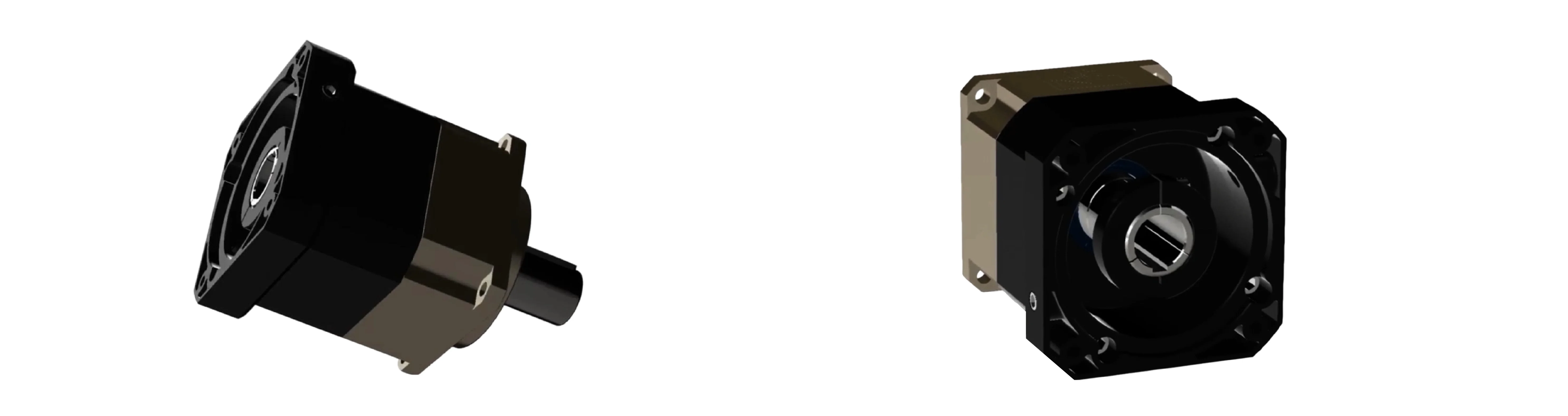
 Reducer (Gearbox)
The primary function of the reducer is to convert the motor’s high-speed, low-torque output into low-speed, high-torque output suitable for vehicle driving applications.
Located at the center of the planetary gear set and directly connected to the motor output shaft.
Distributed around the sun gear and simultaneously meshed with both the sun gear and the internal ring gear.
A supporting structure that carries the rotating planet gears and transmits the output torque.
A ring-shaped gear fixed to the inner side of the reducer housing.
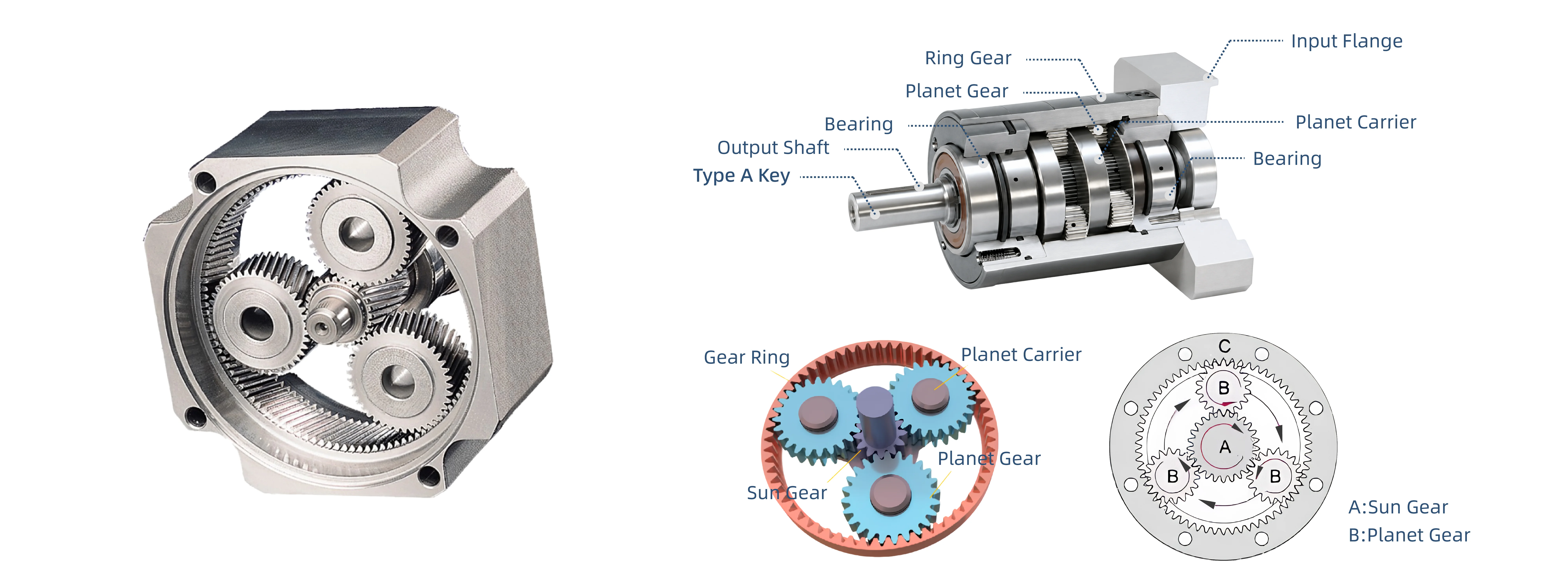
When the motor drives the sun gear to rotate, the planet gears revolve around the sun gear while simultaneously rotating about their own axes.
The torque is ultimately transmitted through the planet carrier to the output shaft, achieving speed
reduction and torque amplification.
 Wheel Hub
The wheel hub is typically manufactured from high-strength alloy materials such as ductile iron or alloy steeto ensure sufficient strength and durability.

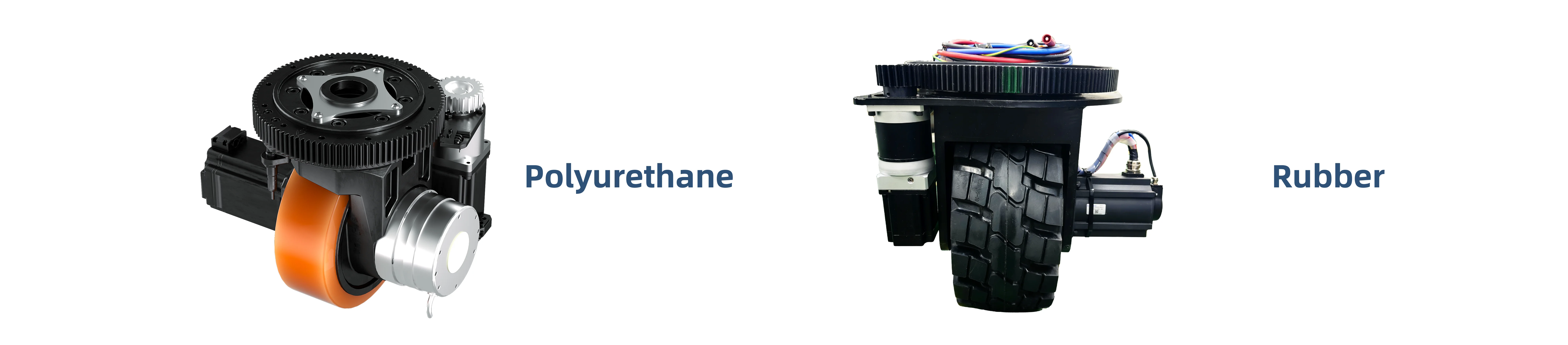
Polyurethane and rubber are commonly used tread materials for AGV drive wheels.
Polyurethane is often selected for its wear resistance, high load capacity, and low rolling resistance, while rubber is often preferred for its shock absorption, floor protection, and low-noise operation.
Depending on the module design, load capacity, floor conditions, and application requirements, wheel diameters may range from approximately 150 mm to 600 mm.
The brake system is an important safety protection mechanism for the drive unit and typically adopts a spring-applied electromagnetic brake.
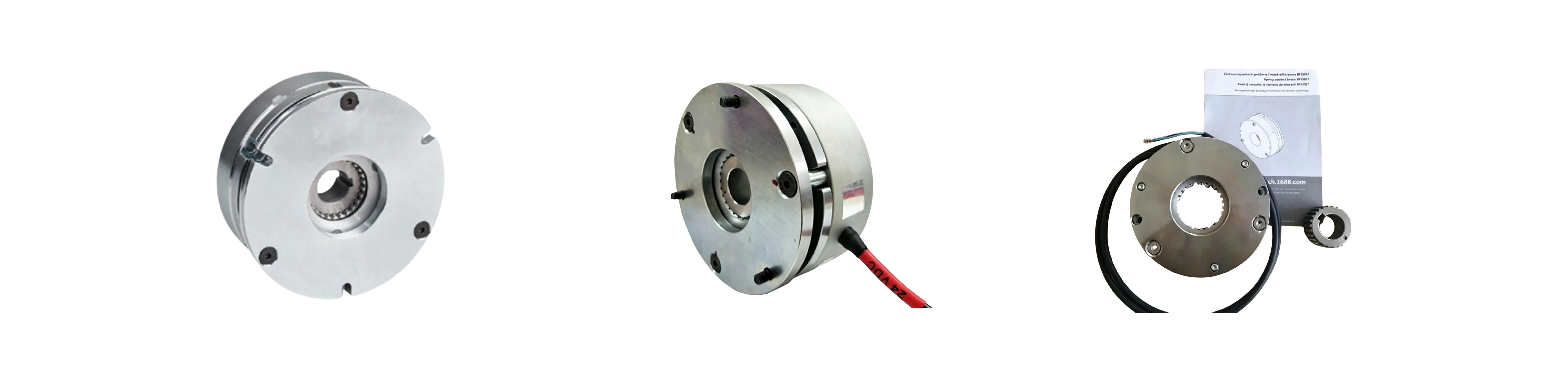
The brake is mounted on the motor shaft and integrated into the drive transmission system.
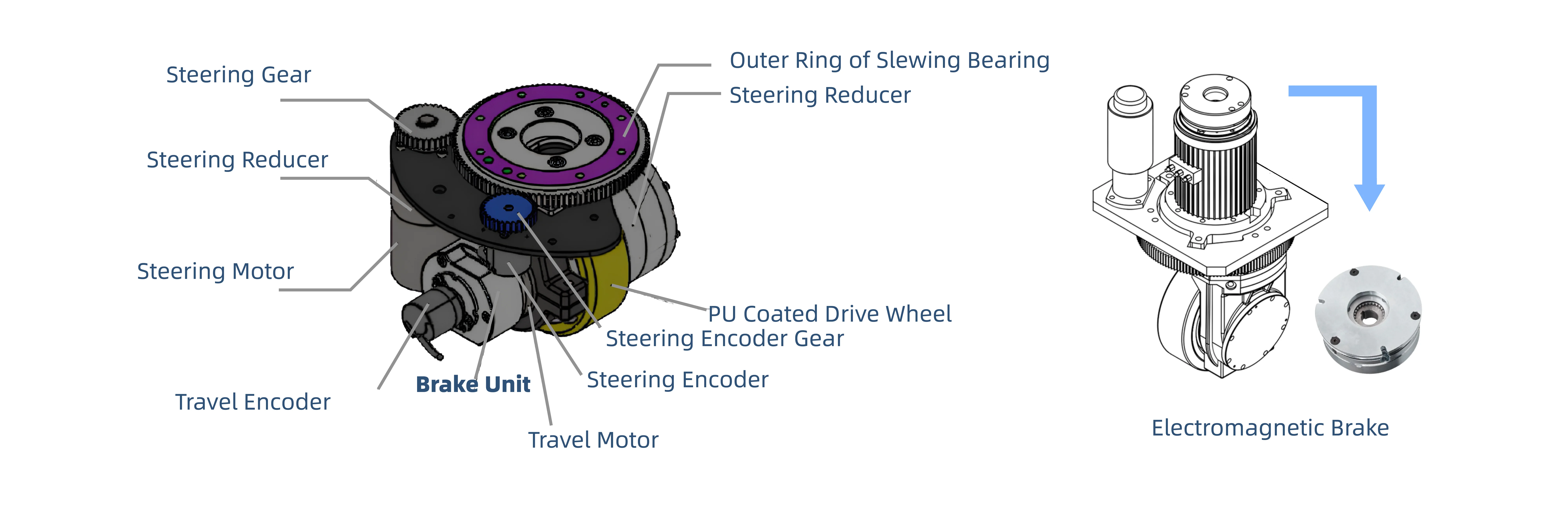
When the electromagnetic coil is energized, a magnetic field is generated that attracts the armature plate, overcoming the spring force and disengaging the friction plate from the brake disc.
When the electromagnetic coil is de-energized, the spring force presses the friction plate against the brake disc, locking the drive shaft through friction and thereby achieving parking braking.
The brake system is an important safety protection mechanism for the drive unit and typically adopts a spring-applied electromagnetic brake.
Spring-guided or dual-guide suspension structures are commonly adopted, allowing the wheel module to undergo limited vertical movement while maintaining stable contact between the wheel and the ground.

For heavy-duty wheel modules, the suspension system may utilize multiple damping rods and compression spring structures arranged in a triangular configuration. Through the coordinated action of guide blocks and guide rails, vibration isolation performance can be improved.

Mechanical Structure of the Steering Unit
The outer ring of the slewing bearing is fixed to the vehicle chassis, while the inner ring is connected to the steering assembly, allowing the wheel module to rotate about the vertical axis.
The outer ring is secured to the chassis, while the inner ring supports the steering assembly.
The bearing elements support rotational movement and carry both axial and radial loads.
The gear ring meshes with the steering pinion gear to transmit steering torque.
A structural mounting component used for installation and fixation of the slewing bearing.

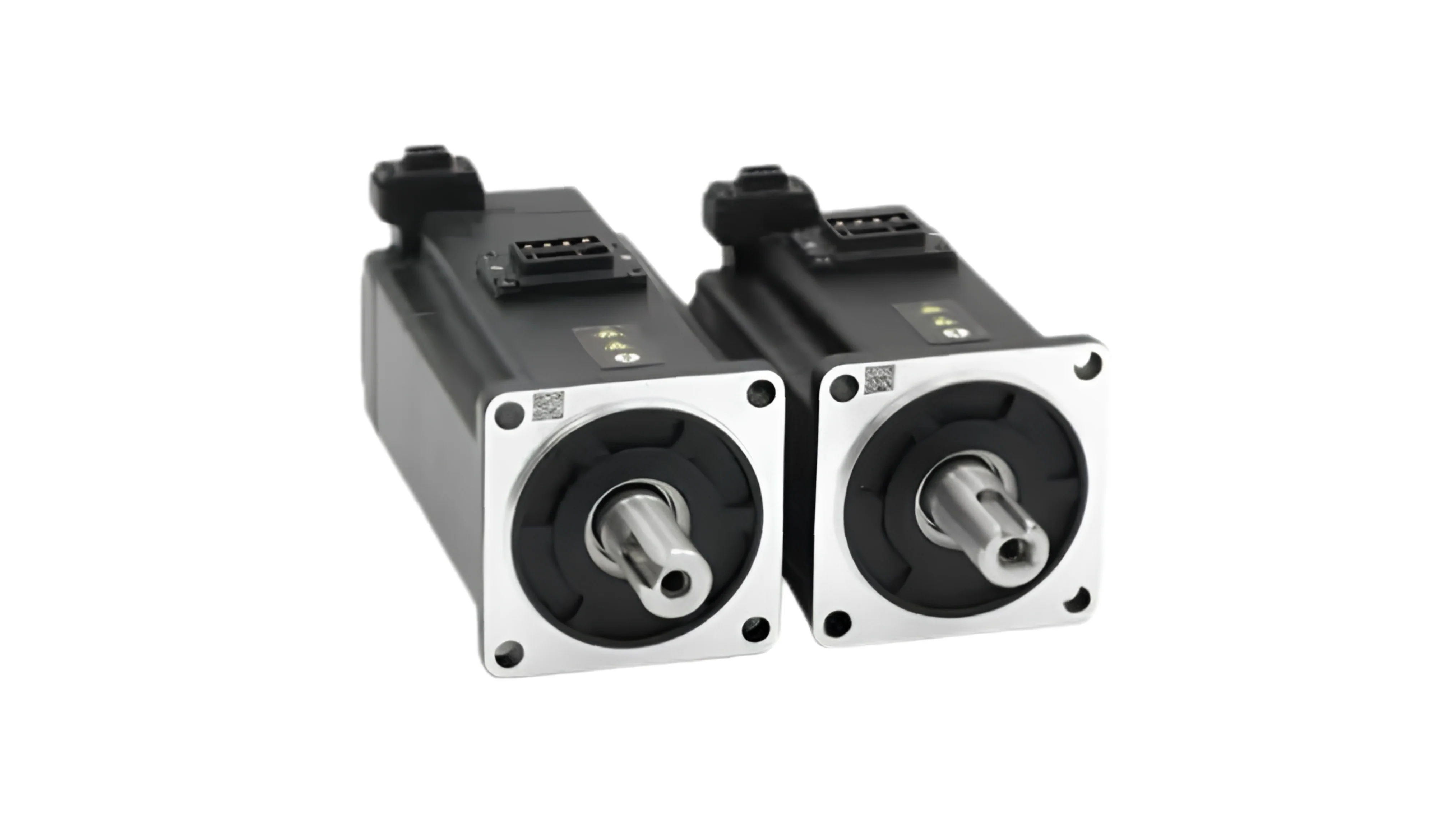
High-precision servo motors are typically used for steering control.
The steering motor drives the steering reducer and steering gear through the output shaft to control the steering angle of the wheel module.
 Absolute Encoder
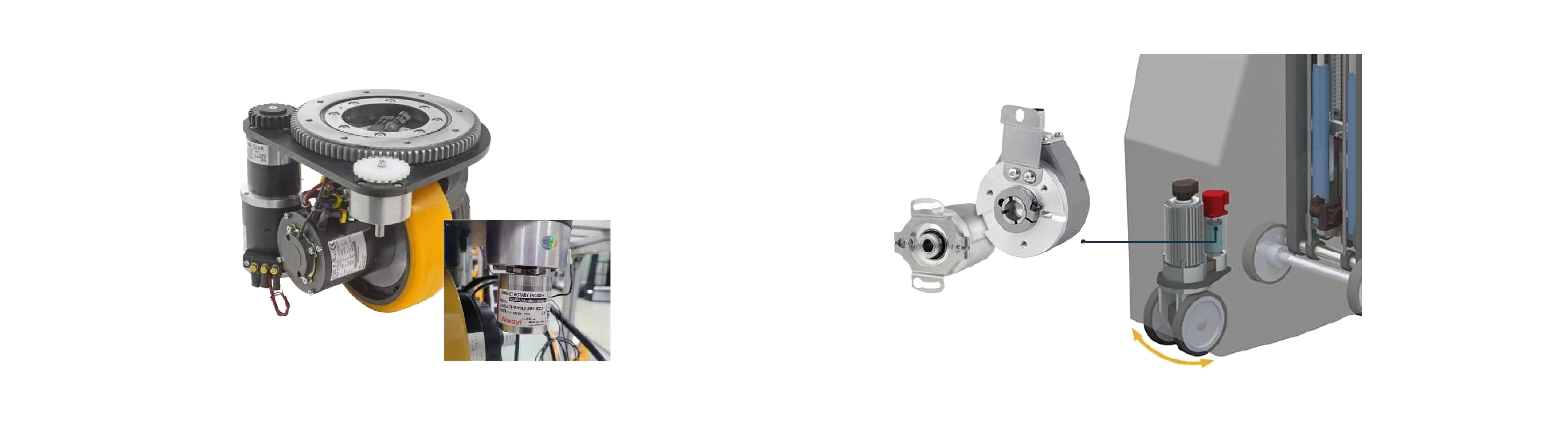
In many servo-based steering systems, the steering motor is equipped with an integrated absolute encoder. The encoder measures the absolute position of the motor rotor, while the control system determines the actual steering angle of the wheel module based on the encoder feedback, transmission ratio, and calibrated mechanical zero.
When a multi-turn absolute encoder is used, the steering position can be retained after power loss or system restart. This allows the control system to recover the current steering angle without performing a homing cycle, enabling faster restart and reducing the risk of directional control errors caused by position loss.
An incremental encoder may also be used in the steering system, but an additional home sensor is normally required. After power-up, the steering mechanism must first return to its reference position for homing before the system can determine the correct steering angle.
Steering Reducer
The steering system uses a planetary gear reducer to reduce motor speed and increase output torque. Its compact structure and high torque density make it suitable for precise steering control within the limited installation space of the wheel module.
High-precision servo motors are typically used for steering control.
The steering motor drives the steering reducer and steering gear through the output shaft to control the steering angle of the wheel module.
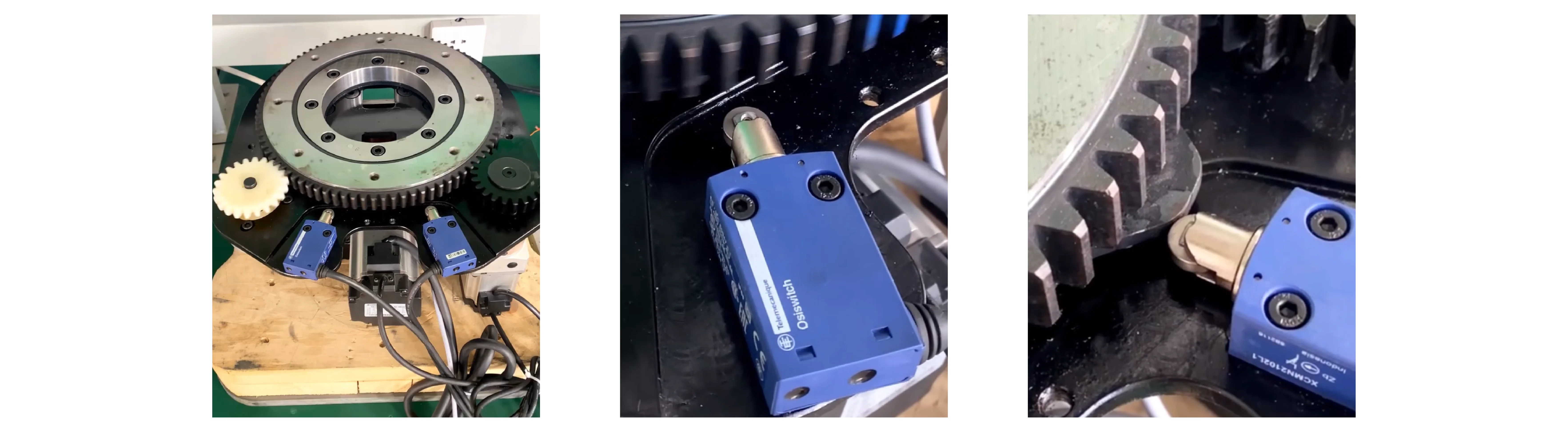
Limit Protection Mechanism
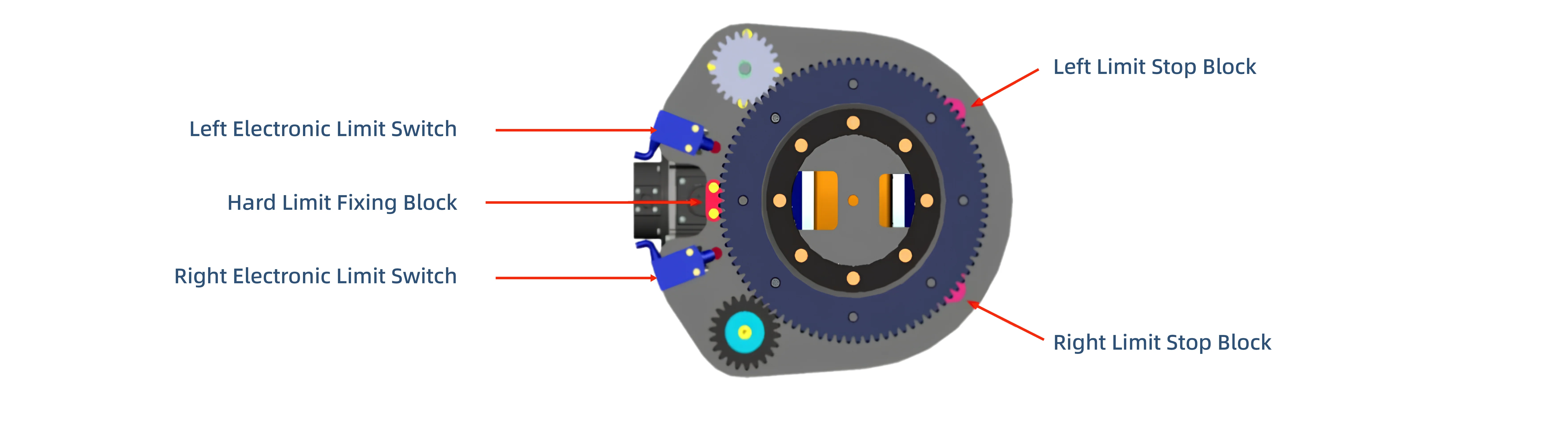
The steering system uses limit protection mechanisms to prevent excessive rotation and protect the mechanical components. The specific configuration depends on the encoder type.
With an incremental encoder, proximity limit switches and mechanical hard stops are typically used, together with a home sensor for zero-position calibration.
With an absolute encoder, software limits and mechanical hard stops are typically used, while home and proximity limit switches are optional.



 Contact Us